

TcpMDT professional
To MDT είναι τεχνικό λογισμικό που τρέχει σε AutoCAD και ZWCAD και περιλαμβάνει πλήθος εφαρμογών και εργαλείων, με χαρακτηριστικά την πληρότητα και την ευκολία στην χρήση. Ο τρόπος που είναι δομημένο σας επιτρέπει να επιλέξετε τις επιλογές που σας ταιριάζουν σύμφωνα με τις εργασίες σας.
Το MDT Professional σας υποστηρίζει σε όλες τις μελέτες σας που περιλαμβάνουν τοπογραφικές εργασίες, όπως έργα οδοποιίας, αποτυπώσεις, κλπ. Επιπρόσθετα της προσομοίωσης του εδάφους, περιλαμβάνει εργαλεία για τον σχεδιασμό των χαράξεων και των διατομών οδοποιίας, των μηκοτομών, τον υπολογισμό των χωματισμών (2D/ 3D), την εικονική επίσκεψη στο έργο και πολλές ακόμα λειτουργίες.

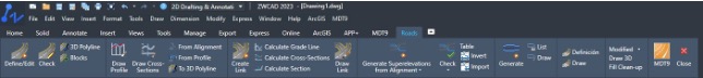
Το MDT v9 υποστηρίζει και την τελευταία έκδοση του ZWCAD PRO 2024
Η νέα έκδοση διατίθεται δωρεάν σε όλους τους χρήστες με ενεργή συνδρομή. Οι χρήστες προηγούμενων εκδόσεων μπορούν να αναβαθμίσουν στην νέα έκδοση.


Supported CAD versions
MDT 9 works with various versions of CAD systems, facilitating the exchange of information between users through drawings in DWG format. They are as follows:
· ZWCAD® Professional Versions 2017 to 2023 (64 bits)
· AutoCAD®. Versions 2010 to 2023 (64-bit)
· BricsCAD® Pro/Platinum. Versions V.17 to V. 22 (64-bit)
· GStarCAD® Professional. Versions 2021 through 2022 (64-bit)
· LusoCAD® Professional. Version 2022 (64-bit)
Supported Operating Systems
MDT 9 supports the following operating systems, 64-bit only:
· Windows 8/8.1
· Windows 10
· Windows 11
General
Unicode
Menus and dialogs are now available in Unicode encoding, for operation in languages that require it.
Units
For linear units you can choose between meters, feet, American feet and inches. Additionally, for the measurement of areas and volumes you can choose between square and cubic feet and yards.
Ribbons
Ribbon-type menus are supported in AutoCAD, BricsCAD, and ZWCAD.
Exporting a list to Word, Excel, or text opens the exported file directly, instead of asking for confirmation.
Proxy server
For Internet connections from updates and web services, it is now possible to specify the Proxy server settings.
Vision
In addition to the existing categories (points, break lines, surfaces, contour lines, profiles) the Control points and Alignment options have been added.
Project
IFC or LandXML import
When you import IFC or LandXML files, the imported items are added to the current project.
BIM Properties
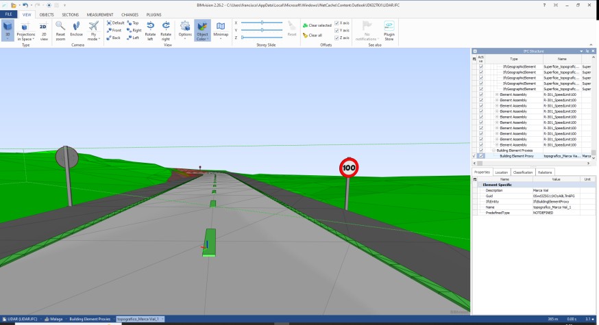
The possibility to consult the BIM properties of the selected object has been integrated into the context menus.
Geodesy
New coordinate systems engine
The coordinate system transformation engine has been updated to version 9 of the powerful PROJ library, which transforms geospatial coordinates from one SRC to another. In practice, this makes it possible to use more than 8,000 reference systems used around the world, including the most recent ones.

These can be projected, geographic 2D, geographic 3D and geocentric. In addition to the EPSG, other authorities such as ESRI and IGN France have been included. The installation also contains multiple grids and geoids from different countries.
In addition, if there are several conversion alternatives, the most accurate option is automatically chosen, without the need to manually select the transformation.
New selection of coordinate systems
The selection of the source or destination SRC can be made by name, region, code or latitude and longitude.

BIM
Issue management using BCF files
MDT 9 allows you to create and edit issues in OpenBIM workflows, managing their details, the associated image and the point of view in files with the standard BCF format, compatible with applications in this sector.

Defining Properties
Several improvements have been made to improve usability and offer more options.
Property Query
You can now query the BIM properties of the objects in the drawing, after you have imported an IFC file.

Export of meshes
In addition to surfaces, binary meshes can also be exported to IFC.
Export of ditches
In the export to IFC of the roads, the ditches are modeled in the event that they are assigned a coating.
Export of horizontal signage
The possibility of exporting drawing objects defined by closed polylines to IFC has been implemented, such as the horizontal signage generated by the Get Modified Terrain command.
Export of 3D objects and vertical signage
3D objects inserted with the corresponding commands, such as vertical signage, luminaires and street furniture are also exported to IFC.
Points
Creating codes
In the code database, a new button facilitates the creation of new codes, graphically selecting blocks or polylines.
New prefixes in point codes
In addition to suffixes in point codes, it is now also allowed to consider numeric prefixes, which facilitate the capture of vertices of multiple entities simultaneously.

Importing Voice Memos from TcpGPS
In importing point files exported by TcpGPS in MDT format, now in addition to importing the images associated with points, your voice memos are also imported.
Insert points on slope
This command now allows a selection of points, which are projected against a polyline.
Filter points
You can now apply the filter to a selection.
Export of points
Added semicolon separator, suitable for CSV format. You can also choose the number of decimal places from the coordinates.
Surfaces and Meshes
Representation with 3D faces
Now assign colors to the different faces, depending on the type of triangle.
Import of meshes
This version allows the import of multiple mesh files, with the possibility of unifying them into one. In addition, you can also import mesh files in ASC format in geographical coordinates.
Move meshes
This new command allows you to create a new mesh by applying a offset in X, Y or Z using a topographic point or a designated point as the source.
New option in parallel displacement
The elevations of the created points, in addition to the existing options of repeat, displace, constant and variable, an option has been added that allows you to specify a slope value.
Cartography and Contour Lines
Identification of high and low areas
In the generation of contour lines, it is now possible to highlight the high and low areas, detecting concentric contours with the indicated equidistance.

Horizontal Alignments
BIM Properties
Listing the alignment indicates its name and you can edit its BIM properties.
Find Alignment
Several improvements have been made, to facilitate the search when there are many alignments in a drawing.
Trim alignment
This new command allows you to extract a span of an existing alignment, specifying its initial and final stations graphically or numerically.
Dimensioning
The dimensioning of alignments now also allows to label its name.
Longitudinal Profiles
Parallel profiling
In obtaining longitudinal profiles, in addition to the profile by the alignment, several files of parallel profiles can be generated at the desired distances.
Automatic update
When updating the surface or horizontal alignment, the profiles drawn in model space can be automatically updated if the user wishes.
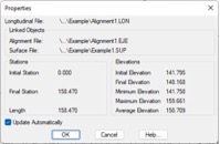
Longitudinal profile properties
This new command allows you to query the properties of the drawn longitudinal profile (length, minimum and maximum elevations, etc.) in addition to controlling whether or not to want the automatic update.
Creation of cartography sheets
A new command has been implemented to create a mapping sheet layout from an alignment, with the size and overlaps specified by the user.

Cartography drawing in longitudinal profile
From the sheets created by the previous utility, longitudinal profiles can be generated that include the corresponding cartography of each sheet.

Longitudinal profile drawing from cross-sections
In the Simple Profile Drawing, you now allow you to select a file of cross-sections, automatically calculating the profile from these.
Labeling of stations determined in the drawing
In the representation of vertices, in addition to the options to label all the cuts or apply a constant distance or codes, a new possibility has been implemented that allows to enter the distances to be labeled.
Projection of points in profiles
You can now select MDT or drawing points. It also allows you to represent blocks or marks on the drawing, as well as the optional labeling of number, displacement, elevation and code.
Projection of longitudinal profile in plan
This new command requests the designation of a drawn longitudinal profile and the horizontal alignment if necessary, drawing a 3D polyline using the elevations of the vertices of the profile.
Longitudinal profile list
The list shows the partial and slope distance between vertices as additional columns.
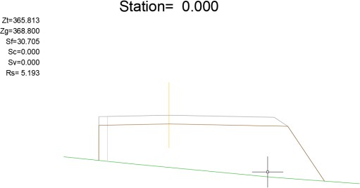
Cross-sections
Automatic update
When updating the surface or horizontal alignment, the profiles drawn in model space can be updated automatically if the user wishes.
Properties of cross-sections
This new command allows you to query the properties of the drawn cross-sections, as well as edit whether or not to want automatic updating.
Graphical designation of stations and distance to alignment
In profiling, the initial and final stations and left and right lengths fields can be defined graphically.
Generation from a surface region
In obtaining cross-sections, if a digital model is selected as the source, an option has been added to select an outline defined by a polyline.
Viewing cross-sections from road segment
From the Review Cross-sections command, selecting the segment, it is now allowed not only to modify the profile of the current stations, but all profiles.
Projection of polylines on profiles
This command allows you to select multiple polylines, by layers or graphic designation, selecting a block to insert in its position on the profile.
Labeling of the slopes in plan
The Draw profiles in plan tool now allows you to optionally label the slopes of each section of the cross-sections.
Vertical Alignments
Parabolic and circular vertical curves
It is possible that vertical curves of the two types coexist on the same alignment.
New options in grade editing
More options for editing vertices have been added to the Vertical Curve command, such as: insert vertex, delete vertex, raise or lower elevation, preview and center on the current vertex.
Labeling of the slopes in plan
The Draw grade line in plan command has a new option that allows you to label the values of the slopes.
Road Sections
Easier section definition
The definition of sections has been simplified from the predefined catalog, so that the platform vectors are automatically assigned to the final station. The values of the cut and fill slopes and the thickness of the roadbed are also assigned.

Import and export of platforms from Excel file
To facilitate the definition of complex type sections, it is now possible to import this data from an electronic sheet in XLS format.
Graphical designation of stations in section assignment
By double-clicking on the cell of the corresponding station, you can graphically designate the point on the drawing. This has been implemented for the definition of: platforms, ditches, cut and fill slopes and road markings.
Pivot vertex for each platform assignment
The ability to designate a pivot vertex for each platform assignment has been included.
Drawing walls with thickness
When drawing the segment, if the walls are thick, they are represented by the thickness of them.
Definition of reinforcements
Added a button to copy the layers of the assigned firm. In addition, in the case in which the option of "Adapt to Terrain" is selected, in the event that the ground is above the section and the reinforcement is applied, a minimum reinforcement thickness has been included, to insert a possible layer, for example chipboard.
Overlaps in the roadbed layers
In the definition of roadbed layers, the possibility of measuring the distance with respect to the start of the hard shoulder or with respect to the upper vector has been included.
Roads and highways
New intersection commands
New utilities have been developed for road intersections, which allow the whole process to be carried out in several steps in a simpler way and with more control on the part of the user.

Road segment file organization
Files that belong to a road segment file are stored in a separate folder, for better organization of project files.
Extract segment file
This new command has been implemented, which allows you to create a new segment file by introducing new initial and final stations.
Horizontal signage
In the Get Modified Terrain command, the drawing of the horizontal signage is done in 3D and represented as polylines.
Pipe Networks
Creation of a section from 3D polylines
This new command allows you to create a pipe span from an alignment and a polyline drawn as a profile, which can include jumps.
Pipe Section Vertices Report
This utility generates a report with the data of the vertices of the selected section, with the possibility of additionally indicating an optional interval.

Pipeline-to-segment conversion
This new option in the Networks command > Export allows you to create a segment file from the selected pipe span.
Setting out
Analyze points with respect to road
This command displays a report with the elevation differences of a set of points provided by file, selection, or designation with respect to a road. The reference elevations are obtained from a surface, the grade or the standard section of the road.

Stake out cross sections
This new command is similar to line staking, but instead of a road segment file, it allows you to work from an alignment and a cross-sections file. It is especially useful for using projects converted from LandXML and other formats.

Point labeling on alignment
The new Label Points on Alignment command allows you to designate points and label their station, offset, projected or geographic coordinates, elevation and optional description.
Creation of points in setting out commands
The Analyze Points command now allows you to draw the points that have been designated graphically, as well as label the calculation information of each point in the drawing.
Quantity take-off
Work executed by cross-sections
This new command allows to analyze the surfaces and volumes between several states, from the existing ground to the theoretical section and a given measurement. It offers the possibility of generating area and volume reports.
Volume calculation
In the calculation of volumes by difference of meshes or surfaces, different layers of cut and fill can be defined by dimension ranges.
In addition, the names of the selected files are displayed.
Frontier lines in volume measurements
In the calculation of volumes by difference of transverse profiles, polylines can be designated to delimit the calculation.
Assignment of work units to walls
From the definition of sections can be assigned to the walls units of works, which are reflected in the quantity take-off reports.
Imagery
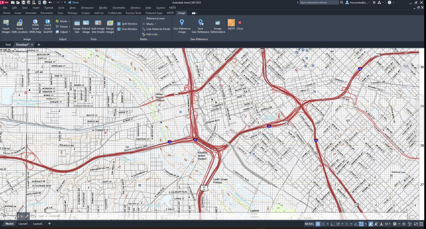
Importing files in GeoPDF format
A new command allows you to insert a georeferenced PDF file into the drawing in its original location.
WMS/WMTS Service Management
The implementation has been revised to make it more compatible, and more services, organized by countries, have been added to the default list.
Maps/Render
New Viewer
MDT 9 includes a powerful new viewfinder that is used in the Route by Terrain and Tour by Road
commands, with among others the following features:
· Display in orthographic and perspective modes, orthogonal views, zoom, free and restricted orbit, mini-map, etc.
· Username-selectable wallpapers (skyboxes)
· General and ambient lighting controls, allowing you to modify its direction, intensity and color. Quality settings and other shading parameters.
· Measurement of 2D/3D distances and areas
· Image capture
Video generation
Now you can choose a resolution of up to 4K, as well as the number of frames per second.

New 3D Object Importer
This application facilitates the import of 3D objects of different origins to incorporate into the project and be represented by the viewer or exported to IFC. It has tools to modify the position, rotation and scale of objects, as well as manage normal vectors, etc.

Importing GPX files
A new command allows you to import files in GPS Exchange Format, widely used by navigation applications. Waypoints are converted to points and each path to a polyline in independent layers.
Slope map
New options to represent the map according to the maximum slope or North-South or East-West orientation, especially useful to study the ideal location for photovoltaic plant projects.
Plots
Generation of 3D constructions
This new command generates a representation of the constructions in 3D from cadastral data, such as the number of floors above ground of each enclosure. The representation can be as solids or 3D faces, and optionally the current surface is used as a base elevation.

Conversion of plots from drawing
The possibility of recognizing not only the geometry and names of the plots, but also their identifiers or cadastral references has been added.

Export of swimming pools
In the export of plots to GML, possibility of exporting the pools annexed to the buildings to be exported.
Utilities
Save sheets in paper space
A new command has been created that allows you to create a paper-space presentation for each of the sheets created.
Drawing crosses and labeling frame
A number of changes have been made to improve usability and make them more versatile.

